
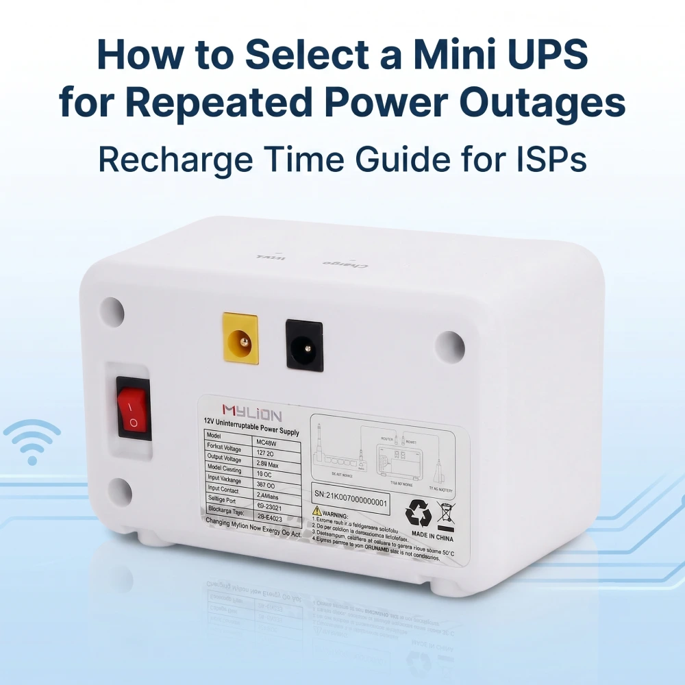
When power fails several times a day, Mini UPS selection is not only about how long a router or ONT can run from a full battery. The system must also recover enough energy after power returns to handle the next outage.
This makes Mini UPS recharge time especially important for ISPs, telecom operators, FTTH providers, network equipment companies, system integrators, and distributors working in markets with frequent power cuts.
For telecom operators and ISPs, MYLION provides Mini UPS solutions designed for routers, ONTs, CPE equipment, and DC-powered communication devices in frequent power interruption environments.
Why Repeated Power Outages Create a Different Backup Power Problem
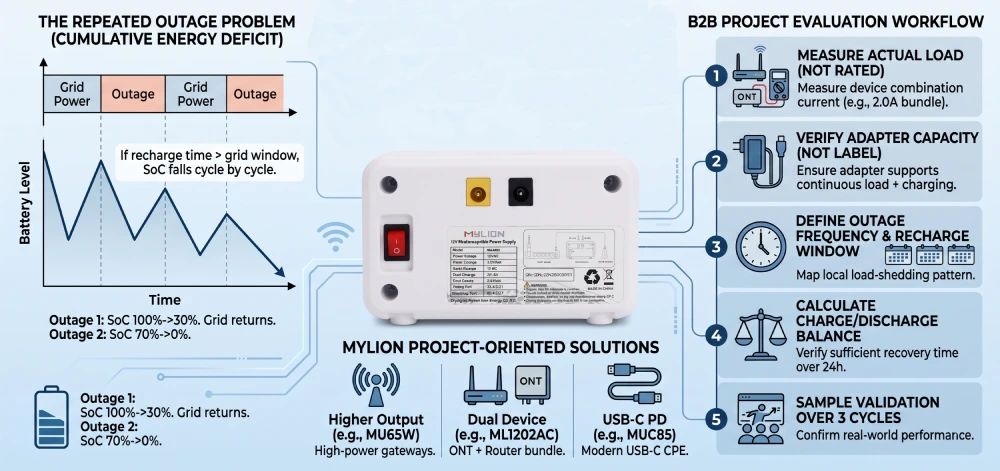
A single outage starts with a battery at a known state of charge. Repeated outages may not.
Grid power → Outage → Battery discharge → Grid returns → Partial recharge → Next outage
If the battery uses more energy during each outage than it can recover before the next one, the available backup reserve gradually falls.
That means a Mini UPS may successfully support a router and ONT during the first outage but provide less runtime during the second or third outage of the day.
For broadband operators, this changes the selection requirement. Instead of asking only for a certain number of backup hours, the project should also define how much energy is used during an outage and how much can realistically be restored before the next outage.
What Does Recharge Time Mean for a Mini UPS?
Recharge time is the period required to restore battery energy after an outage. It is not simply a fixed number determined by battery capacity.
AC power → Adapter → Mini UPS → Router / ONT / CPE
When external power is available, the connected equipment still needs power. The Mini UPS supplies the load first, while the battery is charged according to the available input capacity and system design.
This means recharge performance should be evaluated under the real operating load, not only with the Mini UPS sitting on a test bench without a connected device.
Key Factors That Affect Mini UPS Recharge Time
The following factors have the greatest practical impact on recovery between outages.
Factor | What It Changes | Practical Impact |
Battery energy used | Determines how much energy must be restored | A short outage requires less recovery than a deep discharge |
Battery capacity | Determines the available energy reserve | Larger capacity can provide longer runtime but may require more energy to recover after deep discharge |
Charging capability | Controls how quickly energy can return to the battery | Higher appropriate charging capability can reduce recovery time |
Connected load | Uses part of the available input power | A high-power router or gateway may leave less power available for charging |
Power adapter | Sets an important input-power limit | An undersized or marginal adapter can restrict charging performance |
Battery state of charge | Determines the starting point for recovery | A battery at 70% needs much less recovery than one near its low-energy limit |
Temperature | Can affect charging behavior | Real installation conditions should be included in validation |
Charging control and efficiency | Make charging non-linear in real use | Theoretical recharge calculations should be treated as estimates |
The important point is that battery capacity alone does not determine repeated-outage performance. A Mini UPS with more stored energy may provide excellent runtime from a full charge, but the complete system still has to recover that energy within the available grid period.
Why the Power Adapter and Load Matter During Recharging
The power adapter is often overlooked when customers evaluate Mini UPS recharge time.
Assume a router comes with a 12V adapter rated at 3A. That does not mean the router continuously consumes 3A. The adapter rating indicates its available output capability, while actual router consumption may be significantly lower and may vary during operation.
Adapter → Mini UPS → Network equipment
The adapter may now need to support several demands at the same time:
Connected load + battery charging + system losses + operating margin
This is why replacing a router’s power adapter with another adapter purely because the voltage matches can be risky. Voltage, current capability, connector, polarity, Mini UPS input requirements, and the complete power path should all be checked.
The issue becomes more important with dual-device installations. In an FTTH installation using an ONT and a separate Wi-Fi router, their combined actual load affects not only backup runtime but also how much input capacity remains available after grid power returns.
The maximum ratings printed on two output ports should not be added together automatically. The Mini UPS must support the required simultaneous load within its approved total-power and port limits.
For repeated outages, a technically suitable adapter therefore contributes to two objectives: keeping the equipment powered while grid power is present and allowing the battery to recover efficiently enough for the next outage.
How to Evaluate a Mini UPS for Repeated Power Outages
A useful evaluation does not begin with the largest battery. It begins with the actual equipment and local outage pattern.
Step | Verify | Why It Matters |
1. Define the load | Device model, voltage, normal current, peak current | Determines electrical compatibility and power demand |
2. Check the power path | Original adapter, connector, polarity and cable | Determines whether the complete system can operate correctly |
3. Define backup demand | Target runtime and number of simultaneous devices | Determines the required usable energy |
4. Define outage pattern | Typical outage duration, outages per day and recharge window | Shows whether the battery can recover between events |
5. Validate the configuration | Mini UPS + adapter + cable + actual equipment | Confirms real operating behavior before rollout |
For a router-only application, the load may be relatively simple. For an ONT-and-router bundle, both devices should be evaluated together. An ISP standardizing backup power across thousands of subscribers should also identify the main ONT and router combinations used in its network instead of assuming one configuration will work with every 12V device.
When the actual current is uncertain, measured power or real-device testing is more useful than relying only on the maximum current printed on the original adapter.
Where MYLION Mini UPS Solutions Fit
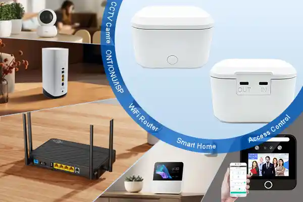
MYLION Mini UPS solutions are designed for B2B applications involving routers, ONTs, ONUs, modems, gateways, CPE, Wi-Fi equipment, CCTV, IoT devices, and other compatible DC equipment.
Different network installations need different product directions. A compact router installation, a high-power broadband gateway, an ONT-plus-router bundle, and a 48V wireless communication device should not automatically use the same Mini UPS.
MYLION’s documented Mini UPS product families include several application directions:
MYLION Product Direction | Example Models | Typical Application Direction |
Standard 12V Mini UPS | MU26W, MU48W, MU68W | Routers, ONTs, ONUs, modems and standard CPE |
MU65W, MU35W, MU35L | Higher-load routers, gateways, modems and CPE | |
12V + USB mixed-output Mini UPS | MUJ46-2A, MUJ435-2A | A 12V network device combined with a compatible USB-powered device |
Dual 12V network backup | ML1202AC | Selected ONT + router or other dual-12V installations |
USB-C PD Mini UPS | MUC85 | Compatible USB-C-powered routers, CPE and newer broadband gateways |
24V / 48V telecom Mini UPS | MU248 | Selected wireless CPE, radio, bridge and professional communication applications |
These models should not be selected by model name alone. The standard 12V family and the higher-output 12V family serve different load ranges, so a high-power gateway should be matched based on continuous and peak current rather than simply choosing the product with the largest battery.
For professional telecom devices that operate at higher DC voltages, the MU248 represents a 24V/48V project direction for selected wireless CPE, radios, bridges, and related communication equipment. These projects require dedicated verification of the equipment, interface, environment, target market, and approved product status.
Device load → Adapter → Mini UPS output → Required runtime → Outage frequency → Recharge window → Sample validation
Specific model availability, battery capacity, charging current, interface configuration, certification status, and current recommendation status should be confirmed against the latest approved MYLION product data before commercial deployment.
FAQ
Q1: How long does a Mini UPS take to recharge?
Q2: Does a larger Mini UPS battery always perform better during repeated outages?
Q3: Can a Mini UPS recharge while powering a router or ONT?
Q4: What happens if another outage occurs before the Mini UPS is fully charged?
Q5: How do I calculate the recharge time required between two outages?
Q6: Does the router's power consumption affect Mini UPS recharge time?
Conclusion
For repeated power outages, backup runtime is only half of Mini UPS sizing. The second half is whether the battery can recover enough energy before the next interruption.
The practical evaluation is straightforward: measure the load, define the outage duration, check the recharge window, verify the adapter and Mini UPS power path, and then test the complete configuration through more than one outage cycle.
For ISPs and telecom projects, this approach provides a much stronger basis for selecting and standardizing Mini UPS solutions than comparing battery capacity or a single full-charge runtime figure.



 English
  简体中文
简体中文  Deutsch
  Français
  Italiano
  Español